
Automation
(Last updated: Monday Sept. 07, 2009)
Using CAI's WebControl
I found a rather interesting device, the CAI WebControl board. I purchased it on Amazon.com (WebControl ($35 plus S&H)). It's an embedded web server with 8 inputs, 8 outputs, 3 analog inputs, 8 DS18B20 temperature probes and 1 one-wire humidity probe (a $15 Honeywell probe). Yup, looks like it supports all of that at one time! I'm definitely going to purchase a few more of these.
Here are the documents in one file (.tar.gz - gzip'd and tar'd). The file contains:
- CasaRemote-Webcontrol.pdf
- HowtoWriteGUICodeforWebControl.pdf
- WebControlPLCUserGuide3-00-00.pdf
- WebControlUserGuide2-03-00.pdf
- WebControlUserGuide2-03-03.pdf <- Latest and greatest, matches my V3.03 firmware.
- WebControlUserGuide.pdf
I'm not sure which files are which. One interesting thing to note. The main web page uses ajax to update the status of each interface. That can become a standard interface to the and would look something like this:
http://webcontrol.uucp/api/status.xml?rand=0.8621719880887507The random number is to get around caching issues in browsers. Each time you call the URL you need to have a different random numeric value.
Random technical details
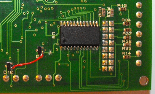
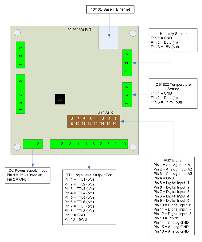
I've already poked around the board to see what it has and the PCB is rather interesting. It has 7 main connectors. There is one connector for DC power (6v - 9v DC). I'd recommend a heat sink for the pwoer transistor next to the power connector. With my 7.5v/1A power supply the transistor was slightly uncomfortable to the touch. The RS232 and RS485/RS422 don't have the driver chips installed. There is one set of connectors (only counts as 1) for the output, there is one IDC connector and I'll guess that's for input (digital and analog input). There's 1 (3 wire) connector for the temperature probes (can't be passive) and 1 (3 wire) for the humidity probe (more details later). The are 3 additional jumpers. One is probably the in-circuit programming header and I'm uncertain what the other two are for yet (perhaps RTFM ;-) ). There is also a 4 postion dip switch which is probably for the RS485/RS422 section (biasing resistors perhaps).
I think the CPU used is a PIC 16F88A and that the RJ45 jack contains the ethernet cpu, IO chip and magnetics. I'm guessing that it's one of those serial to Ethernet jacks. Either that or its a Microchip ENJ i2c setup. I'll investigate that more later.
Like I said this little board has tremendous value for the money. I certainly could match this price if I built my own board.
Fix
 A fix for
inaccurate temperature probes. More details later.
A fix for
inaccurate temperature probes. More details later.
Ports
PLC
6 WebControlTM PLC Programming
The WebControlTM PLC firmware can be programmed to execute programmable logic sequences, including comparison and sub routines. This is the major change from the BRE(Boolean Run Engine) version firmware. WebControlTM PLC uses assembly like PLC language. It starts with "START" and finishes with "END". The PLC program is pasted into the web GUI. WebControl will automatically store it into its EEPROM so that if recycle power will not lose the program. The limitation of the PLC is 4000 line of code. The support for PLC programming is not included in the free support for configuration of WebControlTM PLC.
6.1 The Basics of PLC Programming
A PLC program is made up of main routine and optional subroutines. The main routine is enclosed between mandatory START and END instructions e.g.
START
#main instructions go here
END
If sub routines are used then they are listed after the main routine body. Sub routines start at their label and must end with the instruction RET e.g.
TEST_IO_SUB:
#instructions here
RET
Subroutines can be called from the main program and from within other subroutines. Note that WebControl PLC has a program return address stack depth of 8.
The program control block has a zero bit that is updated implicitly on most instructions. This zero bit can also be used implicitly when using branch and call instructions. E.g. the following test instruction yields a Boolean result which will implicitly set the state of the zero bit. Next a branch instruction is used which branches on the state of the zero bit.
         TSTEQ IP1 1 # sets zero bit based on the result of the test instruction
         BNZ label       # branches to label if zero bit is non-zero

Format of instructions:

label: (optional)
        opcode operands

Labels must be terminated with a colon ':' and can be a maximum of 10 characters.

6.2 WebControlTM PLC Instructions


The following symbols are used in the table below:

d = destination
a,b..c = operands

() = optional, any operand enclosed in parenthesis mean it is an
     optional operand.
[] = delay operator always optional. When the delay operator is used
     on input operands the current value of that input is only used if
     it has had that value for greater than the delay period specified
     between the brackets. When this operator is used on an output
     operand the output value is only set for the period specified in
     the brackets. All delay periods are specified in
     milliseconds. Note that accuracy and timer resolution is
     approximately 100ms, even the delay operator value is in unit of
     1mS..

Opcode               Operands            Description
START                                    Start of main program
TSTEQ                a[] b[] (d[])       Tests if a is equal to b. Boolean result loaded into optional
                                         destination (d). Zero bit updated with result. If test
                                         evaluates to false then the next instruction is skipped.
TSTNE                a[] b[] (d[])       Tests if a is NOT equal to b. Boolean result loaded into
                                         optional destination (d). Zero bit updated with result. If test
                                         evaluates to false then the next instruction is skipped.
TSTGT                a[] b[] (d[])       Test if a is greater than b. Boolean result loaded into
                                         optional destination (d). Zero bit updated with result. If test
                                         evaluates to false then the next instruction is skipped.
TSTLT                a[] b[] (d[])       Tests if a is less than b. Boolean result loaded into optional
                                         destination (d). Zero bit updated with result. If test
                                         evaluates to false then the next instruction is skipped.
TSTGE                a[] b[] (d[])       Tests if a is greater than OR equal to b. Boolean result
                                         loaded into optional destination (d). Zero bit updated with
                                         result. If test evaluates to false then the next instruction is
                                         skipped.
TSTLE                a[] b[] (d[])       Tests if a is less than OR equal to b. Boolean result loaded
                                         into optional destination (d). Zero bit updated with result. If
                                         test evaluates to false then the next instruction is skipped.
SET                  a[] b[]             Sets I/O id a to the value of b.
ADD                  a[] b[] d[]         Adds a and b and puts the result into d. Zero bit updated
                                         with result.
SUB                  a[] b[] d[]         Subtracts b from a and puts the result into d. Zero bit
                                         updated with result.
DIV                  a[] b[] d[]         Divides a by b and puts the result into d. Zero bit updated
                                         with result.
MUL                  a[] b[] d[]         Multiplies a by b and puts the result into d. Zero bit updated
                                         with result.
DEC                  a                   Decrements a by 1. Zero bit updated.
INC                  a                   Increments a by 1. Zero bit updated.
AND                  a[] b[] (d[])       Logical AND's a with b and optionally puts boolean result
                                         into d. Zero bit updated.
OR                   a[] b[] (d[])       Logical OR's a with b and optionally puts boolean result
                                         into d. Zero bit updated.
XOR                  a[] b[] (d[])       Logical XOR's a with b and optionally puts boolean result
                                         into d. Zero bit updated.
BNZ                  (a) b               If the optional a operand is specified it is tested for a non
                                         zero value. If a is not specified then the zero bit is tested for
                                         non zero. If true then program jumps to label specified in
                                         operand b.
BZ                   (a) b               Same as BNZ but tests for zero value.
CNZ                  (a) b               Same as the branch instruction but calls a subroutine
                                         instead of branching. See section on program address stack.
CZ                   (a) b               Same as above but tests for zero result.
CALLSUB              a                   Calls subroutine with label a. See section on program
                                         address stack.
GOTO                 a                   Branches to program address specified by label a.
DELAY                a                   Delay instruction, delay specified in 1/1000 seconds.
NOP                                      A no operation instruction.
RET                                      A return from subroutine instruction.
EMAIL                a                   Sends email, a = index of message to send.
END                                      End of main program. This instructions will set the program
                                         counter back to zero and the program will start executing
                                         from the beginning.

Operands

An operand can be any of the following:
- a signed 32 bit decimal number. e.g. 100 or 1 or 0 etc.
- a hexadecimal number. e.g. 0xABF.
- a date stamp in the format MM/DD/YYYY e.g 02/10/2010
- a time stamp in the format HH:MM:SS e.g. 20:25:00
- a day of week identifier enclosed in single quotes e.g. 'sun'. Day of week identifiers are 'sun' 'mon' 'tue' 'wed' 'thu' 'fri' 'sat'
- an I/O identifier that is a place holder for the real I/O value that the PLC engine will get at runtime. Valid I/O identifiers are explained next below.
6.3 WebControlTM PLC I/O Identifiers
The following are the valid I/O identifiers OP1 TTL Outputs 1...8 Valid range 0 - 1 OP2 OP3 OP4 OP5 OP6 OP7 OP8 IP1 TTL Inputs 1...8 Valid range 0 - 1 IP2 IP3 IP4 IP5 IP6 IP7 IP8 AIP1 Analog Inputs 1...3 Valid range 0 - 1024 AIP2 AIP3 T1 Temperature sensor inputs 1...8 Valid range -550 - +1250. T2 Note that temperature values are specifies in 10's of degrees. So to test for 21.6 degrees C you would use the value 216. T3 T4 T5 T6 T7 T8 H1 Humidity sensor valid range 0 - 100 EM1 Email identifiers 1...8 EM2 EM3 EM4 EM5 EM6 EM7 EM8 CD Current date mm/dd/yyyy format CT Current time hh:mm:ss format CDW Current day of week CH Current hour of day CM Current minute of hour CS Current second of minute CDAY Current day of month CMONTH Current month of year CYEAR Current year VAR1 32 bit signed integer variables 1...8 VAR2 VAR3 VAR4 VAR5 VAR6 VAR7 VAR8 RAM1 32 bit signed integer general purpose RAM 1...8. Delay operator not valid on these. RAM2 RAM3 RAM4 RAM5 RAM6 RAM7 RAM86.4 WebControl PLC Examples
Sets output 1 if temperature T3 is greater than 20.6 degrees and clears OP1 if T3 is less than 20.6 degrees.Flashes output 2 at a rate of 1Hz. (Please note OP2[500] has no space in between).START TSTGT T3 206 OP1 ENDTo setup a momentary output on OP3 of 1 second the following rule should be used: Note you may change the momentary length to 0.5s by change the value from [1000] to [500]. OP3[1000] has no space in between.START TSTEQ OP2 0 OP2[500] ENDTo send email 1 when T3 - T2 >= 20 degrees you would use:START TSTEQ OP3[1000] 1 SET OP3 0 ENDThe above rule is a bit too simple because an email will constantly be generated while RAM1 is greater than or equal to 200. (20 degrees in this case) So to gaurd against that the following logic should be implemented:START SUB T3 T2 RAM1 TSTGE RAM1 200 EM1 ENDSTART SET RAM2 0 LOOP: SUB T3 T2 RAM1 TSTGE RAM1 200 RAM1 GOTO SEND SET RAM2 0 GOTO LOOP END SEND: TSTEQ RAM2 0 RAM2 EMAIL 1 GOTO LOOP6.4.1 WebControl PLC Example 1, Parallel I/O
This simple program performs 4 separate I/O checks and sets O1 to O4 states depending on the state of some inputs.The assembly language written for the above scenarios would be as follows:OP1 is set if T3 > 50 OP1 is cleared if T3 < 50 OP2 is set if IP1 == 1 for more than 300ms OP2 is cleared if IP1 == 0 OP3 is set if AIP1 + AIP2 > 1024 OP3 is cleared if IP4 == 1 OP4 is set if OP1 == 1 OP4 is cleared if OP1 == 0START: CALLSUB checkOP1 CALLSUB checkOP2 CALLSUB checkOP3 CALLSUB checkOP4 GOTO start END checkOP1: TSTGT T3 500 O1 RET checkOP2: TESTEQ IP1[300] 1 OP2 RET checkOP3: AND AIP1 AIP3 RAM1 TSTGT RAM 1024 BNZ l1 TSTEQ IP4 1 BNZ l2 RET l1: SET O3 1 RET l2: SET O3 0 RET checkOP4: TSTEQ OP1 1 OP4 RET6.4.2 WebControl PLC Example 2, Sequential I/O
The following simple program shows how to set-up sequential I/O.The assembly language written for the above scenario would be as follows:OP1 is set when IP1 rises from 0 to 1 OP4 is cleared when IP1 rises from 0 to 1 OP1 is cleared when O4 == 1 OP2 is set when T3 > 25 AND OP1 == 1 OP2 is cleared when OP1 == 0 EMAIL1 is sent when OP2 is set O4 is set when OP2 == 1 for more than 1 secondSTART BNZ IP1 start l1: TST IP1 1 BZ l1 SET OP1 1 SET OP4 0 l2: TSTGT T3 250 RAM1 AND OP1 RAM1 BZ l2 SET OP2 1 EMAIL 1 l3: TSTEQ OP2[1000] 1 BZ l3 SET OP4 1 SET OP1 0 END6.4.3 WebControl PLC Example 3, Traffic Lights
This example will let pedestrian to push a button to change the light on a busy street, so that he can cross the street safely. IP1 hooks up to the pedestrian crossing button. If someone pushed cross button, the street will have amber light on for 10 seconds, then red light to stop all the cars, allowing pedestrian to cross street in next 30 seconds. At the end of 30 seconds, it will flash the amber and red light for 5 seconds. VAR1 in the main program will let the crossing light turn on every 100 seconds, does not matter anybody push the crossing button or not. OP1 Red + Pedestrian crossing light OP2 Amber OP3 Green IP1 Pedestrian Push ButtonSTART CALLSUB LIGHTS_GO loop: SET VAR1[10000] 1 loop1: TSTEQ IP1 1 BNZ sr BZ VAR1 sr GOTO loop1 sr: CALLSUB STOP GOTO loop END LIGHTS_ST: SET OP1 1 SET OP2 0 SET OP3 0 RET LIGHTS_GO: SET OP1 0 SET OP2 0 SET OP3 1 RET LIGHTS_AM: SET OP1 0 SET OP2 1 SET OP3 0 RET STOP: CALLSUB LIGHTS_AM DELAY 5000 CALLSUB LIGHTS_ST DELAY 60000 CALLSUB LIGHTS_AM SET RAM2 5 flash: XOR OP2 1 OP2 DELAY 500 DEC RAM2 BNZ flash CALLSUB LIGHTS_GO RET6.4.4 WebControl PLC Example 4, Time based Control
This example will have four subroutines. WebControl PLC will continuously loop through them. The "hourly" routing will compare analog input 1 and analog input 2, if A1 > A2, send an email notice 1. You can use similar logic to adjust your solar panel orientation each hour, etc. The "period" subroutine will turn on night light after 18 hours and turn it off at 5AM. The "monthly" routing will check the "salt low" sensor AIP3 on the water softener and send email notice 2. The "yearly" routing will ring the New Year's bell connected to OP8 on each and every New Year's Day for the whole day!;***************************************************************************** start callsub hourly callsub period callsub monthly callsub yearly end ;***************************************************************************** hourly: tstne RAM1 CH goto t1 ret t1: set RAM1 CH TSTGT AIP1 AIP2 EMAIL 1 ret ;***************************************************************************** ;* ;* subroutine will turn on night light after 18hours and turn it off at 5AM. ;* The "monthly" routing will check the "salt low" sensor AIP3 on the water ;* softener and send email notice 2. ;* ;***************************************************************************** ; period: ; tstge ch 18 RAM2 ; 18 == 10 PM not 18 hours nop ; tstle ch 5 RAM3 ; 5 == 5 AM nop ; OR RAM2 RAM3 OP3 ; Output 3 on if RAM2 or RAM3 is true, else OP3 off ret ; ;***************************************************************************** monthly: tstne RAM4 CMONTH goto t2 ret t2: set RAM4 CMONTH TSTLT AIP3 20 EMAIL 2 ret ;***************************************************************************** yearly: tsteq CMONTH 1 RAM2 nop tsteq CDAY 1 RAM3 nop AND RAM2 RAM3 OP8 ret ;*****************************************************************************6.4.5 WebControl PLC Example 5, Battery Charger
This is a PLC program to charge 3 serially connected NiMH batteries. First, it tries to discharge the batteries individually. If any battery discharged to 1V, it will stop the discharge and start charging. When each cell being charged to 1.25V, it will stop charging. We assume the A1, A2, and A3 being calibrated to 1V=100. The measurement on the battery 2 is the total voltage of battery 1 and battery 2. And the measurement on battery 3 is the total voltage of all three batteries. This example will individually discharge and charge each battery.start set op1 1 set op2 1 set op3 1 set RAM1 0 set RAM2 0 set RAM3 0 loop: cnz o1 check_b1 cnz o2 check_b2 cnz o3 check_b3 goto loop end check_b1: BNZ RAM1 c1 tstle A1 100 RAM1 bz e1 c1: tstgt A1 125 bnz e1 set o1 0 set o4 1 e1: ret check_b2: BNZ RAM2 c2 sub A2 A1 RAM4 tstle RAM4 100 RAM2 bz e2 c2: sub A2 A1 RAM4 tstgt RAM4 125 bnz e2 set o2 0 set o5 1 e2: ret check_b3: BNZ RAM3 c3 sub A3 A2 RAM4 sub RAM4 A1 RAM4 tstle RAM4 100 RAM3 bz e3 c3: sub A3 A2 RAM4 sub RAM4 A1 RAM4 tstgt RAM4 125 bnz e3 set o3 0 set o6 1 e3: ret6.4.6 WebControl PLC Example 6, RFID reader and browser Control
For office door using RFID reader, as well as allowing operator remote browser control, the following program provided the example. RFID reader's NC (normally connect) output connects to IP1 on WebControl digital input. A 2.2K pull-up resistor also connected between IP1 and 5V. In this way, each time a valid RFID tag sensed, a TTL "1" feeds to WebControl IP1. Remote operator can also open the door by using browser set OUTPUT TTL1 to on. OP1 connects to the door open switch. TESTEQ logic will make sure the OP1 is an 1 second momentary output. "LIGHTS" subroutine is for light control outside the office door; the light is on at 7PM and off at 5AM.START CALLSUB LIGHTS TSTEQ RAM1 0 CALLSUB SET_OP1 CALLSUB CHK4LOW TSTEQ OP1[1000] 1 SET OP1 0 END CHK4LOW: TSTEQ IP1 0 SET RAM1 0 RET SET_OP1: TSTEQ IP1 1 RAM1 SET OP1 1 RET LIGHTS: TSTGE CH 19 RAM2 NOP TSTLE CH 5 RAM3 NOP OR RAM2 RAM3 OP3 RET
Other Links
- Appliance Module - Washing machine interface. I could use this for my washer and dryer.