Automation
(Last updated: Sunday, April 28, 2019)
Notes on nostalgia
While I'm enjoying this trip down memory lane and getting some personal history shared and restored don't think this is my attempt to say that things were better back when I was a kid or that I had worse. This is just my notes on restoring the system. It is 'what it is' comes to mind. Meaning this was as good as it got for those of us doing embedded systems. I do enjoy today's systems with things like the Arduino (quick and dirty), Raspberry Pis and the ESP32, ARM and PIC32 chips. I can toss an inexpensive chip at a problem and solve a lot by doing it in software and in a higher level language.
Sardis ST2900

When I graduated from college as an EET I had the typical run of 'you have no experience' that many graduates run into today. And while today's graduates have better resources than I had, I did manage to do one thing right. I built an EPROM Burner and wrote the code in 6502 assembler for my Atari 800XL. That helped me to get a job with Micro-Comm in East Brunswick NJ. This Micro-Comm made communications equipment for the newspager industry. Since this was the early days of the microcomputer I got to learn all sorts of interesting things; protocols, hardware and software. One of the interesting computers I got to use was the Gimix Ghost running OS-9 Level II (Multi-user, multi-tasking). This was a 2MHz 6809, 8 bit, based computer, it had 2 Meg of RAM (at a time when 64k cost more than $100), a 20M hard disk, 8 serial ports and a parallel port. This was our development machine. We ran 7 people off this machine for development and communications. I really wanted one but it was expensive. One interesting thing about the machine was that it's IO boards had their own CPUs. Even today it's a hard machine to find. But along the way I ran into a strange little computer call the ST-2900 by Sardis Technologies (David C. Wiens). It could run the STAR-DOS, Flex or OS-9 operating systems. The OS-9 was the version from Radio Shack, used on the Coco computers. This version was less expensive than buying OS-9 from Microware but was the same OS-9. With just a little tweeking of a few of the modules you could gen (cobbler?) an OS-9 disk that would turn the ST-2900 into a smaller version of the development system we ran on the Ghost (no CPUs on the IO devices and less memory).

So I purchased a ST-2900 and got to work. I had to find a case and a power supply with enough power for the computer and the floppy drives. Then I needed to build the connections to the serial ports and the parallel ports. Then wire the floppy drive cable and power the drives and the computer and hook it up to the serial port. I ended up creating a hodge-podge of 40T - 5 1/4 inch, 80T - 5 1/4 inch and 80T - 3 1/2 inch drives (6 drives total) on the cable. 3 1/2 inch drive were new and we had a few spare. I had to have the 40T and 80T, 5 1/4 inch drives as the rest of the systems we worked with supported these formats. And yes, it's possible to support more than 4 drives on a drive cable. If I recall correctly, you could have 8 drives (multiplexed).
Once the system was setup, it was time to start up the computer. I hooked up a terminal (I now use a PC, usb serial dongle and something like Putty), setting the terminal to 9600 & 7N1 and if all went well you were greeted with a simple 'CW? ' and the cursor. That meant you now had access to ST-MON and could do various commands to boot the computer. I recall writing a simple assembly language program to start and stop each floppy drive's motor. This allowed me to check that I had built the cable correctly.
Note: One thing to note, the Sardis documentation says that you can change the terminal settings by jumpering the IPx pins a certain way. Dave says that the settings were accidentally hard coded in 2.04 to 9600, 7, N, and 1.
The next part is a little fuzzy. I recall booting the OS-9 conversion disk and then building the OS-9 boot disks. I recall this being quite difficult and I must have spent more than a week failing to boot the system into OS-9. I do recall that at some point I was able to get the system to boot. Since I still have the disks I know I must have done something right. ;-).
While all of this was a nice walk down memory lane it also serves as a reminder of what I'll soon run into. I'm working on getting these machines up and running. Which means I need to find some drives, power, a case and make this bootable. At the moment getting a new triple output (+5, +12, -12v DC) power supply isn't cheap. At the time they were as common dirt and about as cheap. Yes, I am thinking of using a simple PC power supply (see note below).
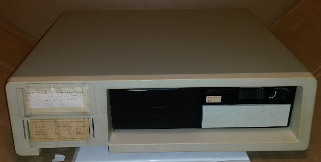
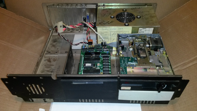
Scratch that, a bit more cleaning up in the garage and I've found a Sardis ST2900 in a PC clone case. I had forgotten that I managed to scrounge around some spare parts and put the whole thing into a case.

And with age some things wear out. Looks like a number of the RAM chips no longer work so I'll need a trip to Jameco to buy some used 4164 and 41256 chips. Preferably 120ns or better.
Specs
- CPU - Motorola 68B09, 8 Bit, 2MHz.
- RAM - 64K 150ns DRAM
- USART - 2 serial port via the 2681
- VIA - 6522
- Floppy - FDC1793
- SAM - 6883 or 74LS783
- RAM Disk - 512K
To get the computer running a lot of prep work was needed. I had to get the correct power supply of, at least: +5v@3A, +12v@0.5A, -12v@0.3A. Then I need a case, the RS232 connectors (I'll use DB9) and at least two 5 1/4" floppy drives. Though I am hoping to get a floppy drive emulator. Then I'd get to work gen'ing a new OS9 boot disk for the ST-2900.
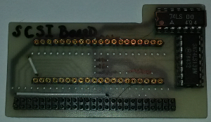
One thing I never got around to when I first put this machine together was adding on the SCSI interface. I had also purchased the SCSI interface for the ST-2900 which consists of a couple of 74LSxx chips and an NCR5380. I'll really need to sit down, add that on to the computer then write the appropriate device driver in 6809 assembly language.
Latest
Sunday, April 28, 2019 - I haven't forgotten about this project. I've just been so @#$%! busy at work that there is no spare time. I did finally find a ROM emulator. And I really need to spend the time to put my parts list for my various computers and EPROM burner. I've been splitting time with assembly language for the Tandy MC-10 (6803) and a 6809 Emulator call SBC09. Both under my Linux system. I've also managed to get the SWTPC emulator working on my Windows machine.
Friday, April 13, 2018 - I found the third Sardis ST-2900 board assembled in a clone PC case with a PS/2 130W power supply and a 40 track 5 1/4 inch floppy drive. I forgot I had built this back in 1984. The case and power supply are cetainly TCF finds. For now I'll go with that.
Okay, one boards returns M2CW? and won't echo back anything (not a good sign -
oops bad RAM). I'll need to look into the RAM and see if it's a corrosion problem
or bad RAM/. The second board is better:
CW?c
ST-MON 2.04 (c) 1984 BY DAVID C. WIENS
=
=E FE7F FE96
FE70 4D4F4E20 322E3034 20286329 20313938 MON 2.04 (c) 198
FE80 34204259 20444156 49442043 2E205749 4 BY DAVID C. WI
FE90 454E5304 3D040D0A 00000000 04FFFF00 ENS.=...........
=
At 9600 7N1 (the IPx pins are set to 9600 8N1, hmph, see note above).
I haven't tried board 3 yet.
I've worked on the SCSI board and figure out most of it. Now I need to
figure out the input lines (some are not obvious). So that down to a few
pins to figure out. I know it's a combination of the 6809 control lines
such as BA, BS, E, MREADY, Q and R/. Now if I can only recall what they
all did.
I now need to clean up the disk drive and I hope I'll have something bootable
soon.
/=============\
Vss I1 40I
I2 39I XTAL
I3 38I EXTAL
I4 37I
BS I5 36I MRDY
BA I6 35I Q
Vcc I7 34I E
A0 I8 33I /
A1 I9 6809 32I R/
A2 I10 31I D0
A3 I11 30I D1
A4 I12 29I D2
A5 I13 28I D3
A6 I14 27I D4
A7 I15 26I D5
A8 I16 25I D6
A9 I17 24I D7
A10 I18 23I A15
A11 I19 22I A14
A12 I20 21I A13
\=============/
/=============\
Vss I1 40I
I2 39I TSC
I3 38I LIC
I4 37I
BS I5 36I AVMA
BA I6 35I Q
Vcc I7 34I E
A0 I8 33I BUSY
A1 I9 6809E 32I R/
A2 I10 31I D0
A3 I11 30I D1
A4 I12 29I D2
A5 I13 28I D3
A6 I14 27I D4
A7 I15 26I D5
A8 I16 25I D6
A9 I17 24I D7
A10 I18 23I A15
A11 I19 22I A14
A12 I20 21I A13
\=============/
SCSI Interface

I have a small 53C80 (SCSI) interface chip board for the ST-2900. Unfortunately I don't have a schematic or description of how to interface it. I've managed to get most of the pinout figured out but not all of it. Add to the fact that I haven't built an interface for a 6809 since 1984 and you have a mystery I need to work out.
Interface
Pin | Description
=====+======================================================================
1 D0
2 D1
3 D2
4 D3
5 D4
6 D5
7 D6
8 D7
9 A2
10 A1
11 A0
12 Vcc
13 Gnd
14 U1 (53C80 p??)
15 U3 (74LS00 P13 - A)
16 U3 (74LS00 P1 - B)
17 U2 (74LS139 P14 - 2A)
18 (Need to derive this from R/)
19
20 U2 (74LS139 P4 - 1Yb)
21 U2 (74LS139 P3 - 1B)
22 U2 (74LS139 P2 - 1A)
     A | B |EOP| Result
     0 | 0 | 0 | 0
     0 | 0 | 1 | 1
     0 | 1 | 0 | 0
     0 | 1 | 1 | 0
     1 | 0 | 0 | 0
     1 | 0 | 1 | 1
     1 | 1 | 0 | 0
     1 | 1 | 1 | 1
53C80 Chip
/=============\
D0 I1 40I D1
DB7 I2 39I D2
DB6 I3 38I D3
DB5 I4 37I D4
DB4 I5 36I D5
DB3 I6 35I D6
DB2 I7 34I D7
DB1 I8 33I A2 (in)
DB0 I9 32I A1 (in)
DBP I10 53C80 31I Vcc
Gnd I11 30I A0 (in)
I12 29I (in)
I13 28I (in)
I14 27I (in)
I15 26I (in)
I16 25I READY (out)
O I17 24I (in)
D I18 23I IRQ (out)
I19 22I DRQ (out)
I20 21I (in)
\=============/
     A2 | A1 | A0 | R/W | Result
      0 |  0 |  0 |  0  | Output Data Register (write)
      0 |  0 |  0 |  1  |
      0 |  0 |  1 |  0  |
      0 |  0 |  1 |  1  |
      0 |  1 |  0 |  0  |
      0 |  1 |  0 |  1  |
      0 |  1 |  1 |  0  |
      0 |  1 |  1 |  1  |
      1 |  0 |  0 |  0  |
      1 |  0 |  0 |  1  |
      1 |  0 |  1 |  0  |
      1 |  0 |  1 |  1  |
      1 |  1 |  0 |  0  |
      1 |  1 |  0 |  1  |
      1 |  1 |  1 |  0  |
      1 |  1 |  1 |  1  |
          SCSI DAUGHTERBOARD FOR THE SARDIS TECHNOLOGIES' ST-2900
          =======================================================

(c) 1988 by Sardis Technologies, all rights reserved


MISCELLANEOUS NOTES
-------------------

1) The ST-2900 SCSI host adapter daughterboard is specifically designed for
   the L5380 chip from Logical Devices Inc., and operation with substitute
   parts from NCR, AMD, etc. is not guaranteed.

2) The terminating resistors (RP1, RP2, R2, R3, R4, R5) can probably be
   omitted if the cable between the ST-2900 SCSI host adapter board and the
   SCSI disk controller board is fairly short and terminating resistor packs
   are installed on the SCSI controller.  This reduces power consumption.

3) The schematics show pin 19 of connector P2 connected to IP3 (at connector
   S1 on the FDC board).  However, do not make this connection unless you
   first modify ST-MON 2.04 to have the baud rate code burned into the EPROM
   so that the baud rate jumpers can be removed from IP3 and IP4.


MODIFYING THE ST-2900 FDC BOARD TO ACCEPT THE ST-2900 SCSI DAUGHTERBOARD:
-------------------------------------------------------------------------

1) Install a female header (1 row x 22 pins, solder tail, designed to accept
   .025" square pins) in the FDC board's prototyping area to mate with
   connector P2 of the SCSI board.  Use the third row of holes from the
   inside -- if you look at the solder side of the FDC board, pin 22 of this
   header will occupy the hole immediately above the letter "v" of the
   markings "rev b".  The header is installed from the component side of the
   FDC board and soldered on the solder side.

2) Wire all 22 pins of the single row female header you just installed for P2
   to the appropriate points on the FDC board as per the schematics.
   Remember to use heavier wires for the +5 and ground pins -- note that the
   two innermost rows of holes in the prototyping area on the FDC board are
   bussed (on the solder side), one for +5v, the other for ground.

3) Install a female header (1 or 2 rows x 20 pins, solder tail, designed to
   accept .025" square pins) in the FDC board's prototyping area to mate with
   some of the pins of connector P1 on the SCSI board.  Use the row(s) of
   holes next to the edge of the FDC board.  Note that this female header
   will not have any wires connected to it -- it is there only to provide
   mechanical support to the SCSI board, so may be shorter or longer than
   specified.


ASSEMBLING THE ST-2900 SCSI DAUGHTERBOARD:
------------------------------------------

1) Install IC sockets for U2 and U3.

2) Install the socket for U1 -- use machined contact IC socket terminal
   strips (eg. four AUGAT 510-AG91D-20 strips), as the crossbars of a
   regular IC socket would be in the way of C1, D2, R4, R5, and especially
   P2.

3) Install resistor SIPs RP1 and RP2 -- note the dot on the component layout
   diagram indicating pin 1.

4) Install resistors R1 to R5 -- note that R2 and R3 must be installed
   vertically (ie. stand on end).

5) Install connector P2 (1 row x 22 pin male header with .025" square pins
   on .100" centers, wire wrap pins).  Insert the connector from the
   component side and solder on the solder side.  Be careful not to get any
   solder on that part of the pins that will be inserted into the matching
   female header.  Make sure the connector is at 90 degrees (right angles)
   to the circuit board.  Cut off flush all 22 pins on the component side
   as U1 will be installed over top of P2.

6) Install the 7 jumper wires which are shown as dotted lines on the
   component layout diagram:
    a) use 22 ga. insulated solid wire for the long jumper sandwiched between
       P1 and RP1, as it carries significant current (to pin 1 of RP2)
    b) there is a very short jumper sandwiched between P1 and RP2
    c) one jumper is near pins 1 of U1 and P2
    d) four jumpers are installed underneath U2, on the solder side of the
       board

7) Install capacitors C1 to C3 -- note that C3 must be installed on the
   solder side of the board so it doesn't get in the way of U2 or U3.

8) Install connector P1 (2 row x 25 pin male header with .025" square pins
   on .100" centers, wire wrap pins).  Insert the connector from the
   component side and solder on the solder side.  Make sure the connector is
   at 90 degrees (right angles) to the circuit board.

9) Install the three IC's into their sockets.

10) Plug the SCSI board into the connectors on the FDC board.


SOURCES OF FURTHER INFORMATION
------------------------------

Kilobaud Microcomputing, May '83 pp.26-40:  OS-9 device driver source code
     for a Western Digital (non-SCSI) hard disk controller

BYTE, March '83, April '83, May '83:  SASI adapter for S-100 bus and CP/M

BYTE, May '86, June '86:  SCSI adapter for 64180 SBC and CP/M


....ST.SCSI.DOC.txt.DW139.881222.2046
